|
Crater OrginsBarry SetterfieldJuly 28, 2012
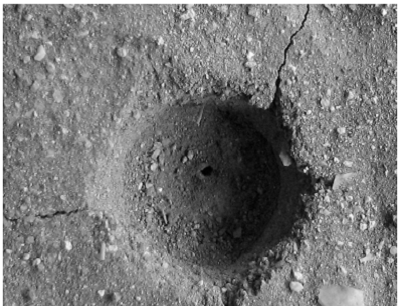
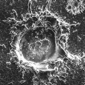
Two Types of CratersApart from volcanism, there are two processes whereby craters can be formed. The best known is from an asteroid or comet impact. The other way, and one that is currently under a lot of study, is through Electric Discharge Machining (EDM). Experimental work done in the laboratory can help distinguish the difference in the craters formed by the two methods. CJ Ransom of the Vemasat Laboratories has produced a variety of craters which have been electrically formed.
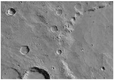
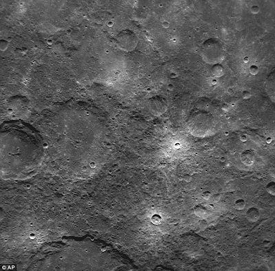
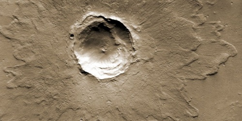
These electrically machined craters tend to have flat floors and more or less vertical walls, which may or may not have a rim made up of debris. The example in Figure I may be compared with many craters on Mars, such as those in Figure II, or Mercury in Figure III.
Figures IV and V provide other examples of craters formed by Electric Discharge Machining. A comparison can be made with craters on Mars, Venus and Mercury.
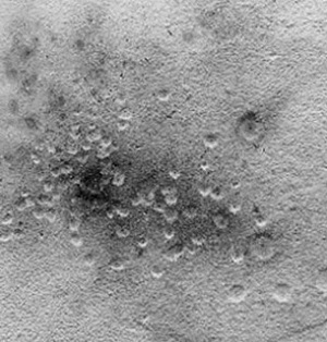
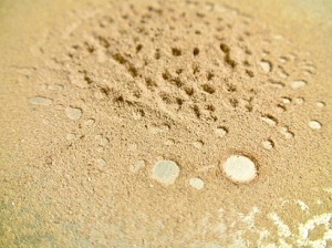
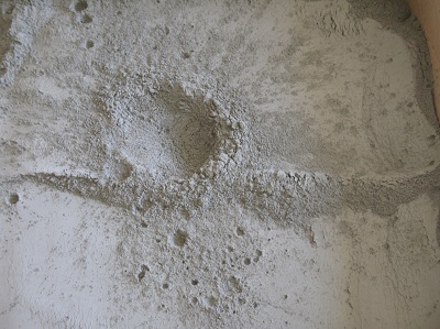
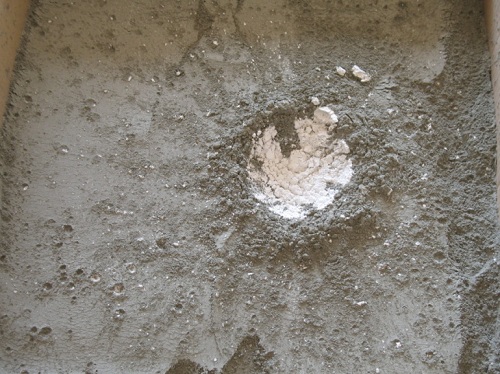
Craters which have been formed by electrical methods can occur singly or in multiples and can often overlap. However, fragmentation of an asteroid before it hits will also reproduce some of these features. So, too, will a swarm of smaller bodies accompanying the larger asteroid on its path to destruction. These swarms of asteroidal material are common in space. Their impact conditions can be reproduced in laboratory experiments using a “meteorite” that comprises a dessert-spoon or table-spoon of slightly compressed, dry cement dust. It is dropped from a height of 4 feet into a pan of dry, unconsolidated, cement dust about 6 inches deep whose surface has been very lightly tooled with a cement worker’s metal float. An example of craters left by a cement dust “meteorite” which broke up in flight is given in Figure VI. Cement dust is used to simulate impact craters because in any such collision, with speeds of up to 45 miles per second, any material is going to be pulverized whether it be soft pumice or alloy steel. So what is needed to reproduce these conditions is a material which has no tensile strength. There is such a material; it is dust. And for practical reasons, cement dust is used as it comes in uniform quality after all lumps have been screened out. All that is needed is one slightly consolidated “meteorite” of cement dust in a spoon, dropped into the pan of cement dust, and these are the results.
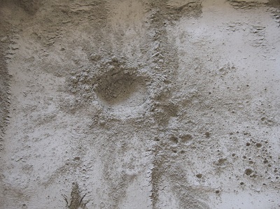
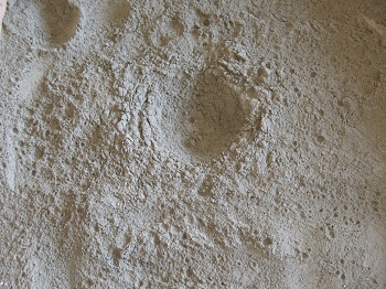
In these experiments, for both the electrically produced and the cement dust impact craters we get the single, the multiple, and the overlapping craters. Splash craters formed as a result of impact also have their counterparts in EDM craters. Figure VII shows a typical bowl-shaped crater, formed in the cement dust experiments. It is accompanied by the usual radiating ridges, rays and the suite of secondary splash craters.
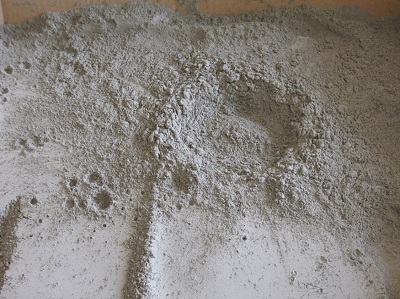
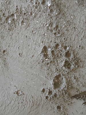
Using cement dust, it frequently happens that limited chains of craters form along with the main crater. This can be seen in Figures VI and VII. It is also possible to have smaller craters form on the wall of the larger one, as in Figure VIII.
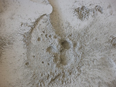
Central peaks are obtained in cement dust experiments where there is an unyielding layer about 3 inches below the surface. This is achieved by using a flat tile or something similar. The typical results are in Figure IX.
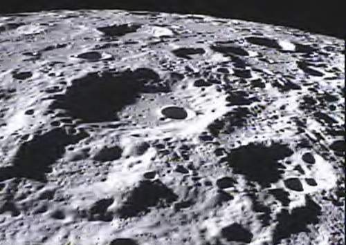
Figure IX should be compared with the craters on the Moon such as the two examples in Figure X.
From these examples, it can be seen both impacts and electrical machining can form bowl-shaped, or ‘simple’ craters, as well as ‘complex’ craters with central peaks and terraces, along with accompanying splash craters and secondary craters on the ring wall. However, there are ways in which bolide, or impact, craters and EDM craters can be distinguished from each other. Electrically machined craters tend to have straight or vertical walls, flat floors and ejecta blankets which may be multiple or overlapping. Some examples of craters from Mars show the multiple ejecta blankets well, such as the Mars crater in Figure XI. In this example the ejecta blankets almost look like flow structures. A single impact event cannot produce this. However EDM can spread many layers of material while the process of forming the crater is in operation. The multiple layers of material are involved in the ejecta blanket are evidence of electrical machining.
This contrasts with impact craters which tend to have complex ridge and ray systems rather than ejecta blankets. These systems in the cement dust experiments shown here are intrinsic features of crater formation via impact. If a meteorite of compressed plaster of Paris powder is used, it is possible to discern where the rays and splash craters come from. Figure XII shows the result.
This gives us definite evidence of an impact meteorite. When nickel-iron bodies, which are the remains of the impact material, are found under the rim, it is an impact structure. This is also evidenced by shocked quartz, as it only forms under impact conditions. It is debris from the surface layers at the explosion site that forms rays and splash craters. The splash craters which formed as a result of the explosion on the impact model only have a small component of meteorite material. This is evident from Figure XIII left where a Plaster of Paris meteorite was again used and a close-up of one group of splash craters is given. Figure XIII right is a group of splash craters on a cement-dust surface that had not been smoothed. The formation of splash craters by impact seen in Figure XIII is similar to those seen on the Moon and Mercury. While this impact feature can also be reproduced by electric discharge machining of craters, the concurrent formation of radiating ridge and ray systems indicates impact, as EDM tends to form more uniform ejecta blankets. Let us examine these ray systems for a moment.
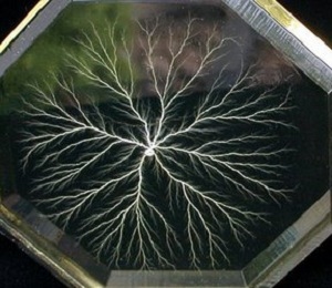
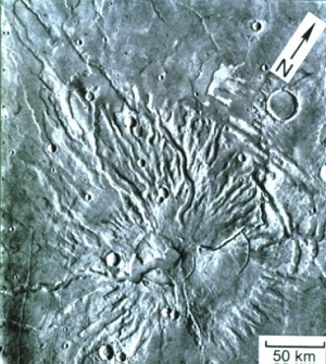
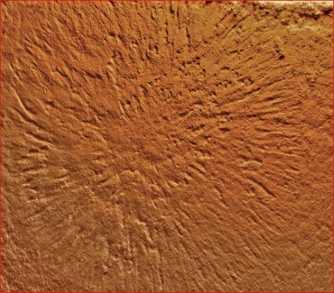
Crater Ray Systems However, many radial channels can also be produced around craters formed by EDM. Many also have a bilateral symmetry. Basically they are forms of Lichtenberg figures. These radial channels or grooves are associated with craters on both Mars and Venus, and probably Mercury.
It is apparent that these radial channels and grooves were made by EDM processes when the craters or other objects at their center were formed. But these radial channels or grooves are different from the fine lines of powdery material thrown out in narrow trajectories which comprise the ray systems of impact craters.
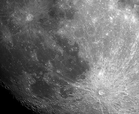
The crater Tycho, on our moon, gives evidence that the ray material was explosively expelled. First, there is the ray-free area around Tycho as discussed in Figure XVI. Second, in one case, the stream of ejecta appears to have partly gone into orbit, forming a ray which can be traced completely around the Moon. As it did so, the Moon rotated underneath the sub-orbital spray of ray material. Since the Moon was rotating on its axis during the time the ray was being formed, Tycho was displaced from the orbital plane of the material by 50 miles. This is the precise distance at which we find the end of the ray passing the crater itself. EDM has not reproduced anything like this. Types of Craters
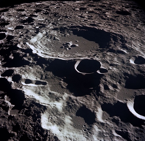
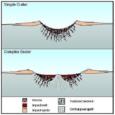
Complex craters have central peaks. However, a study has shown that impact craters on the Moon can only form central peaks when the crater is in the size range of 15 to 80 miles across. From the cement dust experimental data, this may also be an indication of a very dense, solid layer at a depth of about 4 or 5 miles beneath the surface. This may be evidence that the impacting material had to be large enough, and coming in at a high enough speed to penetrate deeply enough for this layer to rebound to form the central peak complex. In contrast, EDM can form craters of any size with central peaks. If the terraces drop vertically, and there is a basically flat floor with a ‘peaked ring’ rather than a central peak complex, the crater may well have been formed by EDM processes. Even detailed studies cannot show how impact scenarios can account for the peaked ring, as can be seen in Figure XVIII. There are many craters on Mercury and Mars in this peaked-ring category, which would indicate an electrical origin. However if the central peak is a single complex, and the crater has a ray system like Tycho or Copernicus, it is probably the result of impact. Crater Features
Rille system on the moon in Mare Orientalae It should be noted that some craters, like Ptolemaeus, Archimedes or Plato on the Moon, have flat floors. This is because the magma from the Lunar interior has flooded the crater bottom. The floor of the crater has the same color as the nearby Mare plain, as shown in Figure XIX. Grooves in the walls of some of these craters, carved by the flying debris on a pattern radial to the center of the Mare, indicate that these craters were there before the molten rock forming the Mare surface was extruded. The molten rock then flooded the floor of these craters.
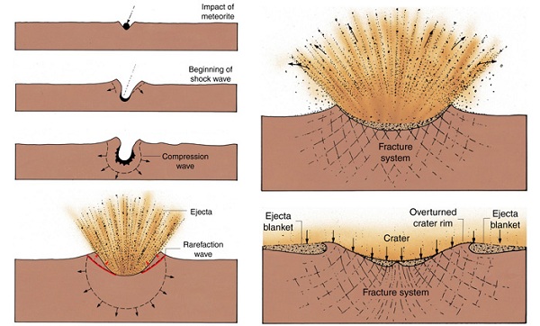
There is another diagnostic feature which attests to the different crater origins. With an impact, the resulting explosion at depth forces the rock layers in the rim at the surface to be upturned and tilted back on themselves. The sequence of events is displayed in Figure XX.
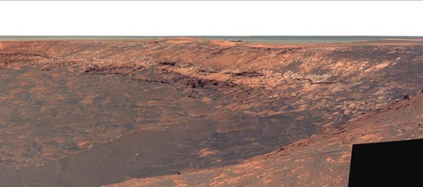
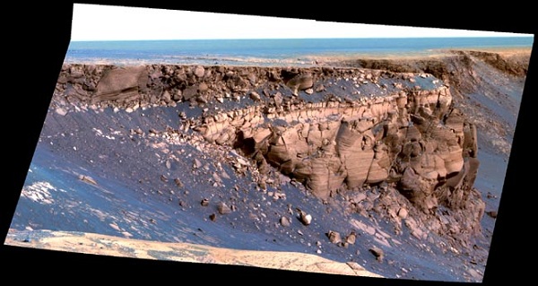
Since the rock strata are turned back on themselves, the strata at the exposed rim will be vertical, not horizontal. In contrast, electrical machining would have carved down through the strata, leaving the sides basically horizontal. In this way, a close-up examination of any crater rim should allow us to tell which method formed the crater. The two photos in Figure XXI, taken by NASA’s Mars Exploration Rover, Opportunity, are of the Victoria crater on Mars. They show that the rim strata are horizontal right around the crater (top). The top photo is of Duck Bay in Victoria crater. The detail in the bottom photo, showing Cape St. Vincent on the rim of Victoria crater, shows that not only are the strata horizontal, but the layering in that strata is also horizontal. That is strong evidence that this particular crater originated from electric machining which cut down vertically through the strata and distributed the debris around the rim.
Further evidence that the Victoria crater was electrically machined can be seen in Figure XXII. Again the horizontal rim strata are in evidence. However, there is another feature which is important to consider: the scalloped edges to the crater rim.
This is entirely consistent with the action of electric machining, and cannot be produced by an impact. Because of all this evidence, it can be concluded that the Victoria crater on Mars was formed by electrical machining processes, not impact. On a very large scale, there are huge circular structures like Mare Imbrium on the Moon, the Caloris Basin on Mercury, or the Hellas basin on Mars.
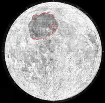
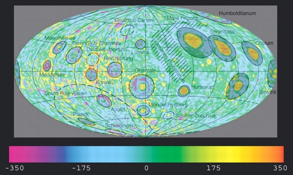
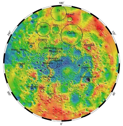
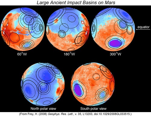
Mare Imbrium outlined on the Moon These vast circular plains, which have been covered with magma from the interior of the planetary body, have been shown to have some kind of massive body, referred to as a mass concentration or ‘mascon’ underneath the structure. The position of mascons on the Moon is shown in Figure XXIII. (The right hand half of the image is the part of the Moon visible from the earth and the left hand side of the picture is the hidden side of the moon). In this illustration it can be seen that the major Lunar Maria -- Imbrium, Serenetatis, Crisium, Smythii, Humboltianum, Humorum, and Nectaris -- all have positive mass concentrations. Mare Orientalae on the far side also has a small mascon associated with it. The other basins seem to have a mass deficit, or not massive body underneath, as shown on the Moon’s hidden side. The mascons on Mercury are in Figure XXIV, while those for Mars are shown in Figure XXV.
It is impossible to form mascons by any EDM process reproducible in the lab, but testify to the fact that a significant portion of the impacting body (probably iron-rich) remains there. Under these circumstances, it is safe to say that, generally, the large circular basins are the result of impact.
Could impact craters and EDM craters have occurred at the same time? Yes, certainly. The disturbances caused by large impacting objects could easily have triggered massive electrical disturbances. These would have been almost guaranteed if the incoming objects had a strong electrical charge. This is evidence that the key times for electromagnetic effects would also be the times when showers of debris occurred from both the Late Heavy Bombardment and the break-ups that gave us the asteroid belt. The differences and similarities from the two methods of crater formation are summarized in the following Table.
So basically, if a crater has any or all of these characteristics it was formed by impact:
If it has any or all of the following characteristics, it was formed by Electric Discharge Machining:
|